Loss of AS332L1 LN-OPG off Brønnøysund, Norway, 8 September 1997
This accident and the loss of 12 lives off the coast of Norway in 1997 had far reaching consequences for the use and regulation of helicopter Health and Usage Monitoring Systems (HUMS).
The Accident
On 8 September 1997 at 06:00 local time, a Norwegian AS332L1, registered LN-OPG, departed from Brønnøysund, just south of the Arctic Circle, for the Norne oil production vessel in the Norwegian Sea. Two pilots and 10 passengers were on-board (AAIB/N 2001: 4). The operator had acquired this aircraft when it absorbed a Norwegian competitor (AAIB/N 2001: 11). It was equipped with IHUMS (AAIB/N 2001: 14).
At 06:50 the crew observed a short illumination from the overspeed (or ‘OVSP’) light (AAIB/N 2001: 7). This light is primarily intended to indicate activation of an engine overspeed protection system (AAIB/N 2001: 13 and Padfield R.R. ‘Finger Trouble in the Super Puma’, Helicopter World, January-March 1990 pp 28-32) but both engines continued operating and they were not able to identify a problem (AAIB/N 2001: 7). The indication was however caused by an abnormal vibration causing a momentary loss of contact between the power turbine and its speed sensing probes (AAIB/N 2001: 98).
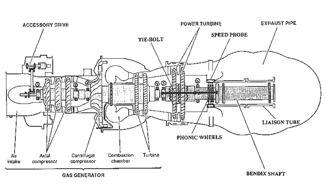
The vibration was due to a failure developing at the gearbox end of the drive system connecting the right hand engine to the main gearbox (MGB). It is believed that two components at the MGB end of right hand high speed input shaft (known as the ‘Bendix shaft’), the splined sleeve and subsequently the splined flange (below), had become cracked to a considerable extent during previous flights.
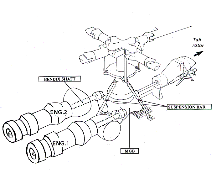
The thin walled Bendix shaft transmits (see below) power from the Makila engine (up to 1742 shp at 22850 rpm) and has flexible bellows (or diaphragms) at each end to allow relative movement between the engine and the MGB (AAIB/N 2001: 11-12).
These bellows are also weak points, designed to fail first. In such an event the longer piece of the shaft is prevented from flailing by a small stub shaft (one protruding beyond the bellows at each end).
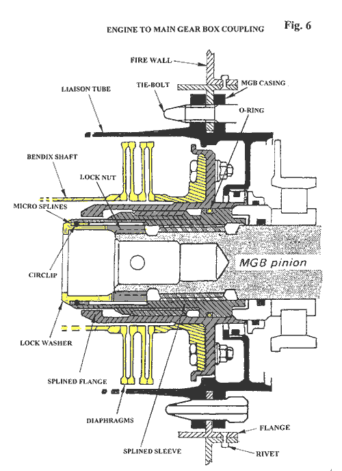
About six minutes after the overspeed light first flickered the splined sleeve and flange deteriorated so as to release a lock washer and circlip (see AAIB/N 2001: Figure 6 above) into the Bendix shaft.
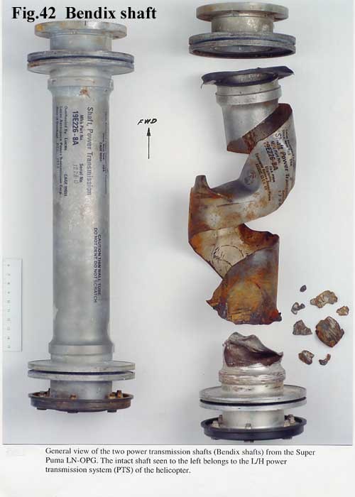
The Bendix shaft severed (see below) under the one tonne static load imposed by the lock washer (AAIB/N 2001: 97-99). The break was between the bellows, meaning that the severed shaft flailed, generating strong vibrations.
If the Bendix shaft fails the most serious hazard is that the power turbine (see below), no longer constrained by the load of the rotor system, could be accelerated by the gas generator exhaust until its turbine discs burst, releasing high-energy debris.
The defence against this is an overspeed protection system designed to shut down the gas generator as the power turbine accelerates above 120% power turbine speed (Nf) (AAIB/N 2001: 13). There were no requirements for the further defence of debris containment when the AS332L was certified (AAIB/N 2001: 24).
Unfortunately the progressive failure in the drive system also damaged the Nf sensors used by both the overspeed protection and Engine Electronic Control Unit (EECU). Due to a flaw in the design, not only did the loss of Nf signal cause the EECU to increase the gas generator speed (Ng), but the overspeed protection system was also disabled.
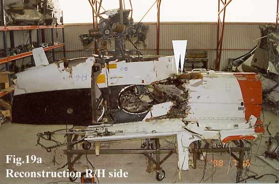
The power turbine accelerates until the turbine discs burst (AAIB/N 2001: 101). The debris cut the flying controls (see AAIB/N 2001: Figure 19a at the top of this page) and the helicopter, which had been flying at 1800ft and 120 knots, went out of control. All 12 occupants died when the helicopter hit the sea about 15 seconds later (AAIB/N 2001: 7), 100 nautical miles from Brønnøysund (AAIB/N 2001: 50).
Safety Issues from the Accident Investigation
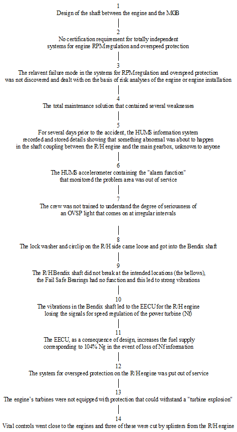
The AAIB/N (2001: 101) identified 14 causal factors (see below). These are broadly listed chronologically.
A prime tecnical objective of the AAIB/N investigation became to identify what initiated the fatigue cracking in the splined sleeve (AAIB/N 2001: 101). A number of potential contributory causes (both production and maintenance related) were considered (AAIB/N 2001: 111-120). The AAIB/N was not able to establish with certainty the initiating factor, but noted two circumstances that they considered potentially relevant (AAIB/N 2001: 4-5):
- Non-conformity of the sleeve’s coating to drawing requirements
- Vibration from the combination of input pinion and 8000rpm gear fitted
The manufacturer has stated that they believed neither factor contributed and instead suggested that the absence of an o-ring from the right hand assembly, omitted during maintenance, was the source of vibration (AAIB/N 2001: Appendix F). The AAIB/N agreed that the lack of o-ring would have hastened crack propagation, but believed it did not contribute to the initiation (AAIB/N 2001: 163).
During the investigation it emerged that increasing vibration trends had been recorded by HUMS on the:
- Right hand power turbine over approximately 160 flying hours,
- Right hand MGB epicyclic module (where the accelerometer is above the right hand MGB input)
- Left hand MGB input
No warning thresholds were exceeded. In the case of the power turbine accelerometers no thresholds were set, the data being solely used to support investigations after other thresholds are exceeded. It should be noted that the contemporary competitor of this HUMS did not have any engine accelerometers. The other two accelerometers had thresholds, but set for the areas of the gearbox they were sited to monitor. So while vibration increases from the right hand input area were tracked, they did not exceed local thresholds (AAIB/N 2001: 18-19).
The right hand MGB input accelerometer, the one closest to the failure, had been unserviceable for around 11 weeks and 430 flying hours (AAIB/N 2001: 19), having only been installed for 18 days before failing on 21 June 1997. The replacement was not ordered however until 24 August 1997, 2 weeks before the accident (AAIB/N 2001: 21).
If this accelerometer had been serviceable in the period leading to the accident, the AAIB/N:
‘…believe that the accelerometer could have recorded and given notification of the trend in question in time to have allowed the accident to be prevented’ (AAIB/N 2001: 163).
Opinion within the HUMS industry confirms that an adequate warning would have been given if the accelerometer had been serviceable (Donaldson P. ‘Did HUMS Sensor Fault Hide Shaft Problem?’, Helicopter World, February 1998, pp50-51).
This accident did lead to a review across the industry that has resulted in ‘considerable improvement in HUMS’ (AAIB/N 2001: 21).
Safety Recommendations
Two of the recommendations relate to the generalities of health monitoring:
Recommendation 34/2001: The Norwegian Civil Aviation Authority, in collaboration with the other civil aviation authorities around the North Sea basin, should assess whether requirements should be introduced regarding the use of HUMS in passenger transportation by helicopter within the area. This assessment should among others cover requirements for serviceability, analysis of data, introduction of industrial standards and standardisation of the requirements within JAA. (AAIB/N 2001: 165)
Recommendation 46/2001: The operator should draw up a strategic plan with clear objectives for the use of HUMS. (AAIB/N 2001: 167)
Two further recommendations are relevant to organisational aspects of the accident:
Recommendation 43/2001: On the basis of this report, the Norwegian Civil Aviation Authority should carry out an assessment of the documented quality system at technical division at [the operator] with regard to appropriateness and integrity. (AAIB/N 2001: 166)
Recommendation 44/2001: The Norwegian Civil Aviation Authority should assess whether aviation companies should be directed to draw up a plan, as part of their flight safety work, of how skills in Human Factors in Aviation Maintenance are to be acquired and integrated. (AAIB/N 2001: 166-167)
The Aftermath
After the accident, as the AAIB/N mention, operators came together to agree what good looked like for maintaining HUMS.
From 2000 this and other operating requirements for HUMS Vibration and Health Monitoring (VHM) became a regulation in the UK.
Contemporary thinking can be found in a paper by our Aerossurance’s founder Andy Evans, then the UK CAA Surveyor responsible for the regulation of HUMS: Managing a Successful HUMS Operation, presented in Australia in 2003 (and cited in the NASA paper Rotorcraft Health Management Issues and Challenges). Evans’ paper drew heavily on research done for a one year MSc research project on ‘Organisational Factors Affecting Helicopter Vibration Health Monitoring’, in particular looking at this accident in Norway and a 1995 UK serious incident. The prior sections of this article are slightly edited from an appendix of that thesis.
A few years later NCAA introduced their own national requirement.
In November 2015, after an extensive collaborative safety initiative, the offshore helicopter safety organisation, HeliOffshore, launched a comprehensive HUMS Best Practice Guide that further raised the bar to standardise and improve HUMS use worldwide.

A requirement for VHM is being extended and expanded across Europe from 2019 with the new HOFO regulations (a new Subpart K of Annex V [Part-SPA] to Commission Regulation (EU) No 965/2012, applicable to CAT, NCC and SPO, following Opinion 04/2015):
SPA.HOFO.155 Vibration health monitoring (VHM) system
(a) The following helicopters conducting CAT offshore operations in a hostile environment shall be fitted with a VHM system capable of monitoring the status of critical rotor and rotor drive systems by 1 January 2019:
(1) complex motor-powered helicopters first issued with an individual Certificate of Airworthiness (C of A) after 31 December 2016;
(2) all helicopters with a maximum operational passenger seating configuration (MOPSC) of more than 9 and first issued with an individual C of A before 1 January 2017;
(3) all helicopters first issued with an individual C of A after 31 December 2018.
(b) The operator shall have a system to:
(1) collect the data including system generated alerts;
(2) analyse and determine component serviceability; and
(3) respond to detected incipient failures.
AMC1 SPA.HOFO.155 Vibration health monitoring (VHM) system
GENERAL
Any VHM system should meet all of the following criteria:
(a) VHM system capability
The VHM system should measure vibration characteristics of rotating critical components during flight, using suitable vibration sensors, techniques, and recording equipment. The frequency and flight phases of data measurement should be established together with the type certificate holder (TCH) during the initial entry into service. In order to appropriately manage the generated data and focus upon significant issues, an alerting system should be established; this is normally automatic. Accordingly, alert generation processes should be developed to reliably advise maintenance personnel of the need to intervene and help determine what type of intervention is required.
(b) Approval of VHM installation
The VHM system, which typically comprises vibration sensors and associated wiring, data acquisition and processing hardware, the means of downloading data from the helicopter, the ground-based system and all associated instructions for operation of the system, should be certified in accordance with CS-29 or equivalent, established by the Agency.
Note: for applications that may also provide maintenance credit (see Federal Aviation Administration (FAA) Advisory Circular (AC) 29-2C Miscellaneous Guidance (MG) 15), the level of system integrity required may be higher.
(c) Operational procedures
The operator should establish procedures to address all necessary VHM subjects.
(d) Training
The operator should determine which staff will require VHM training, determine appropriate syllabi, and incorporate them into the operator’s initial and recurrent training programmes.
GM1 SPA.HOFO.155 Vibration health monitoring (VHM) system
GENERAL
Operators should utilise available international guidance material provided for the specification and design of VHM systems. Further guidance can be found in:
(a) CS 29.1465 Vibration health monitoring and associated AMC;
(b) Federal Aviation Administration (FAA) Advisory Circular (AC) 29-2C Miscellaneous Guidance (MG) 15 — Airworthiness Approval of Rotorcraft Health Usage Monitoring Systems (HUMSs); and
(c) United Kingdom Civil Aviation Authority (UK CAA) CAP 753 — Helicopter Vibration Health Monitoring.
UPDATE 9 May 2020: Ungreased Japanese AS332L Tail Rotor Fatally Failed
Aerossurance is pleased to be supporting the annual Chartered Institute of Ergonomics & Human Factors’ (CIEHF) Human Factors in Aviation Safety Conference for the third year running. We will be presenting for the second year running too. This year our toptic will be the Maintenance Observation Programme concept.

This year the conference takes place 13 to 14 November 2017 at the Hilton London Gatwick Airport, UK with the theme: How do we improve human performance in today’s aviation business?